
Research / Geometric transport
Light through a recess
An oblique ray enters at one point and reaches the exit plane at another. Their sideways separation is enough to explain why two openings of equal area may pass different amounts of light.
Interactive figure / 02
Tilt the incoming light
Look down on the two mouths. The dashed outline shows the exit projected onto the entrance plane. The pale overlap is the part of the entrance that has a clear path through the recess.
Square
4:1 rectangle
Both openings have area 1 and depth 1 in normalized units. The rectangle is 2 by ½. A single direction tilts along its long edge. Each percentage is the fraction of incident power with a straight path through the opening under spatially uniform illumination and perfectly absorbing walls.
01 / Published working paper
What the model establishes
Equal area leaves out information
A direction displaces the projected exit relative to the entrance. For a rectangular channel tilted along its width, the visible fraction is max(0, 1 − d tan(θ) / w), where d is the depth and w the width in that direction. The interactive figure evaluates this single-direction case.
A finite source gives a separate test
The paper integrates over an oblique cone with a 2° half-angle. In its square versus 4:1 rectangle case, the modeled transmission differs by about 23.34 percentage points. The two openings share the same normal, area and depth. A predictor given only those three quantities has to return the same value for both.
The numerical comparison asks a second question. Once shape is retained, how much computation does a given error tolerance require?
Geometry information and approximation cost in recessed-aperture transport
Read revision 8 on Zenodo02 / Proposed physical test
Path A on the bench
The first physical question is whether a measured square–rectangle difference survives the source, mounting and collection uncertainties of a real instrument.
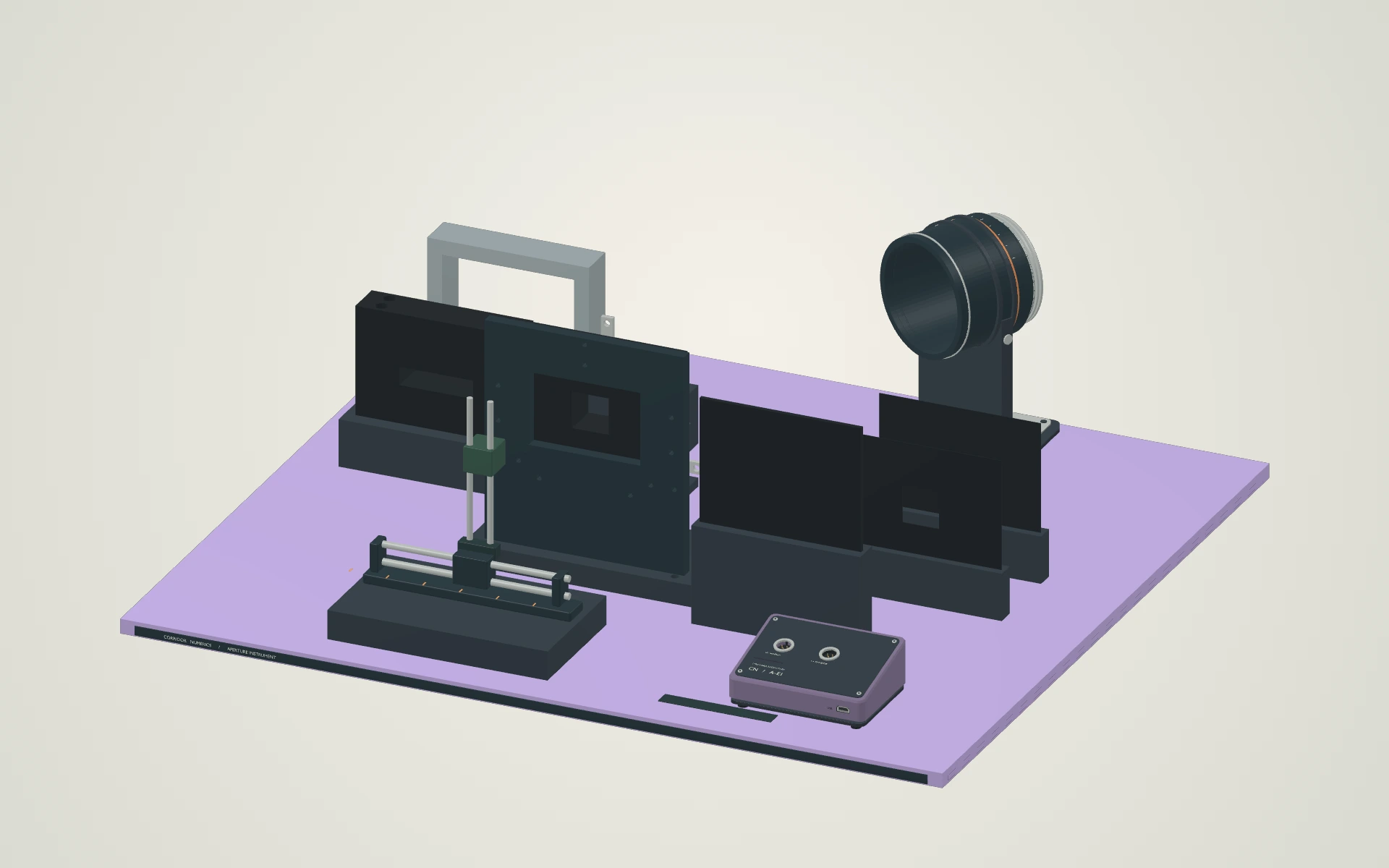
Before exchanging the samples
Measure the actual mouth, depth and wall finish. Map the incident field at the sample, check dark signal, and establish how much of the outgoing light the detector collects.
When comparing the readings
Use the same normalization for both samples. Repeat the exchange and reseat each part. Retain the raw readings, alignment and uncertainty so another operator can reconstruct the difference.